The I-prober 520 Current Probe - PCB trace current measurement
PCB track current measurement
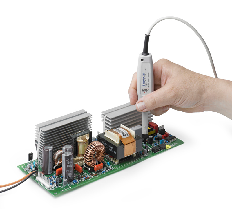
The unique feature of the I-prober 520 is its ability to observe and measure currents flowing in PCB tracks by acting as a "positional" current probe.The magnitude of the signal is critically related to its position relative to the conductor which means that the probe tip must be positioned carefully. The size of the conductor (e.g. the width of a PCB track) also has a significant effect.
This means that the sensitivity of the I-prober has to be adjusted to match the track width when quantitative measurements are required. A calibrator within the control box enables sensitivity adjustment in conjunction with a calibration graph.
The measurement result will also include other field effects present at the tip of the probe and not just that coming from the current through the conductor. This may include DC effects from adjacent magnetized components and from the earth's magnetic field, plus AC effects from transformers and other field radiating sources.
Current in adjacent tracks, or tracks on the opposite side of the PCB will also affect the measurement.
There are potential solutions to these problems. The unwanted DC can be nulled out by observing the measurement without power to the circuit, whilst AC interference can be attenuated using bandwidth filters. The I-prober control box includes a wide range DC offset control and switchable filters.
Nevertheless, the use of the I-prober 520 requires interpretation based upon a proper understanding of circuits and systems. It is a tool for the professional engineer and is not suitable for use by just anyone.